The application of ceramic coating on fired heater tubing and refractory avoids oxidative scale formation and improves heat transfer, significantly optimizing the heater efficiency, lowering fuel consumption, CO2 and NOₓ formation.
This case study pertains to the application of Cetek high emissivity coatings on the radiant tubes and refractory surfaces within the refinery’s fired heaters. The primary objective was to enhance radiant efficiency and facilitate the sustainable operation of the heater for the next 8-10 years.
Nowadays, ceramic coatings are approved materials to increase the energy efficiency of fired heaters or debottleneck the heaters with various limitations, such as bridgewall temperature (BWT), firing duty or uneven heat flux distribution. Initially developed in the 1970s, coatings have found successful use in all heavy industrial applications, including metals processing, aerospace, glass industry, and fertilizers but became especially beneficial in the oil and gas and petrochemical industries.
In some cases, tubes in fired heaters are made of steel that experience oxidation scale formation on the external surfaces. Heavy scale creates poor conductive heat transfer through the tube wall to the process. This leads to over-firing and high BWTs (bridgewall temperatures), eventually leading to a BWT limitation and reduced production rate. High emissivity tube coatings can provide the following benefits:
• Reduce fuel consumption or increase capacity under the same firing
• Increase emissivity of tube surface up to 0.92
• Prevent oxidation scale formation
• Lower BWT and increase radiant efficiency
• Reduce CO₂ and NOₓ emissions
Additional benefits can be provided by high emissivity ceramic coatings applied to the refractory surfaces, which improve radiant heat transfer efficiency to the process over design conditions and extend refractory life.
The fired heaters of this unit consist of four cells with sketches available in the public domain. All cells have double firing with burners located on the bottom. Tubes are made of A335P9 steel alloy, and walls and arch are insulated with castable refractory. The internal division walls and floor are made of insulating firebrick.
Before the project, the refinery had searched for a solution to gain efficiency of its fired heaters and prevent any radiant tube oxidation. This oxidation scale acts as a strong barrier for heat transfer and may decrease radiant coil thermal conductivity.
In the case of no scale formed on the surfaces, it has been calculated that there is a potential gain on radiant efficiency of at least 11.2 % from the initial state throughout the run.
It is worth mentioning that the feed naphthene content, which has a direct effect on the BWT limit, was expected to increase by an additional 5 to 10 vol.%. It allows a wider operational flexibility for the feed selection choice.
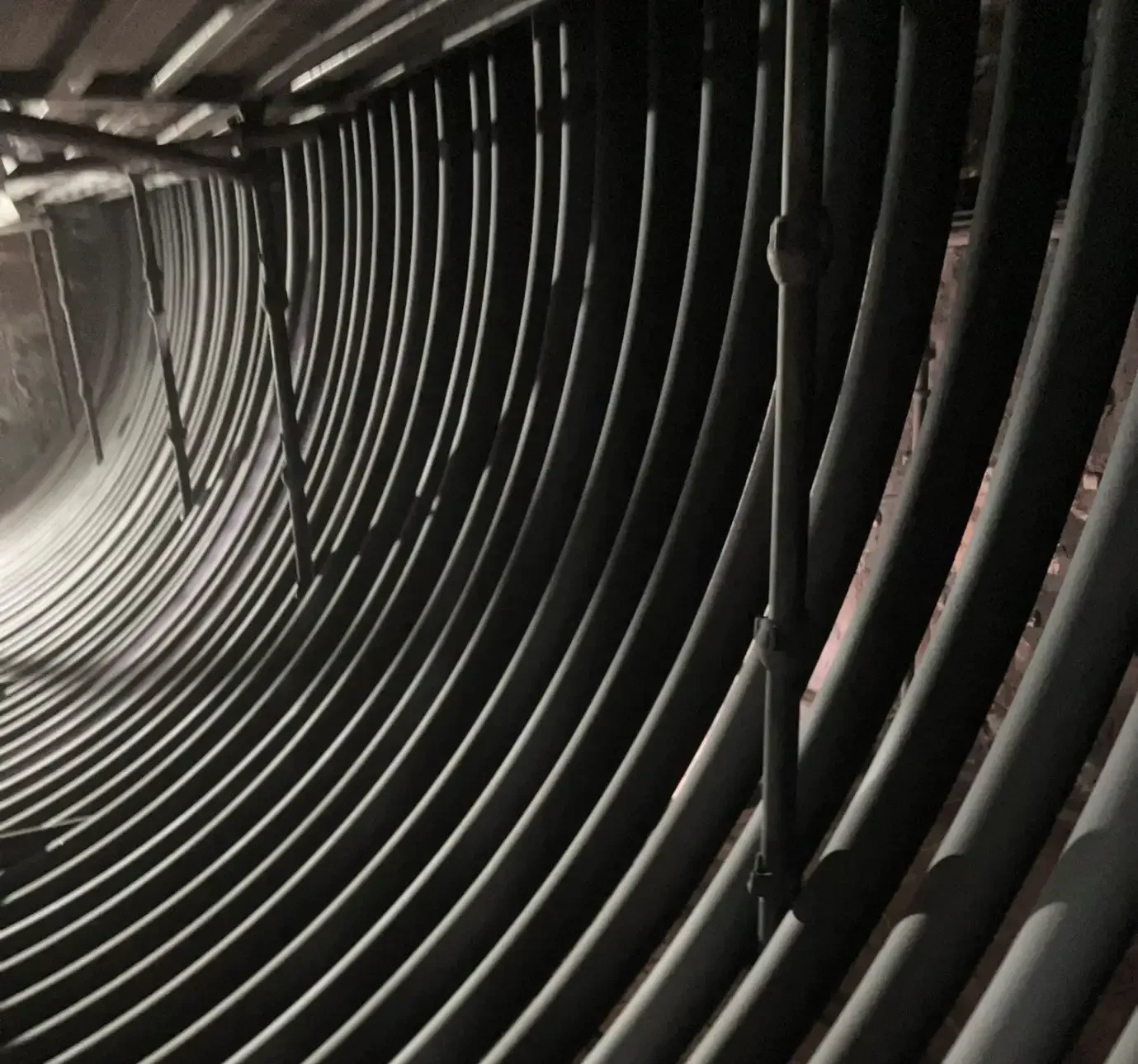
High emissivity coatings were applied to all radiant surfaces in three of four heaters during a major turnaround. A special ceramic coating system was selected for each type of surface. As a first step, tube surfaces were prepared to meet the application standards (see Figure 1).

Figure 1 – Tubes Prepared For Coating
After that, a high emissivity tube coating (TC) was applied.
The result after both tube and refractory application can be found in Figure 2. The application took only nine days, including all steps and phases.

Figure 2 – Tubes (left), refractory (right) after coating
To accurately predict the anticipated outcomes following the application of high emissivity coatings, an infrared inspection was conducted on all process tubes. This assessment was coupled with collecting process data related to heater performance. Post-application, a significant reduction in tube surface temperatures and BWTs was anticipated for all heaters. This reduction was expected to enhance radiant efficiency, enabling the potential for fuel savings or an increase in capacity under the same firing rate.
Figure 3 demonstrates a substantial reduction in tube surface temperatures (averaging more than 1OO°C) following the turnaround, particularly in the context of fuel savings. Furthermore, the temperature distribution along the length of the tubes became more uniform. The determination of tube metal temperature via IR thermography is notably more reliable after coating application, as the oxidation scale is eliminated, and the coating’s emissivity and temperature gradient are well-defined.
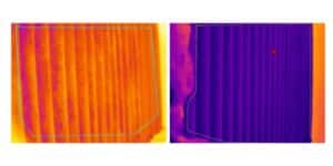
Figure 3 – IR images before (left) and after (right) in interheater.
Following the completion of the project, a visual inspection was carried out. Figure 4 vividly illustrates the noticeable distinction between the uncoated cell and the coated ones. As an additional advantage, the heat distribution along the length of the tubes became more even. Moreover, determining tube metal temperature through IR thermography became possible, owing to the well-established i1T {temperature difference) and a constant emissivity value attributed to the coating.
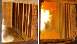
Figure 4 – uncoated cell (left) vs. coated (right)
Data trends on BWT, excess air, combustion air temperature, and fuel consumption were analyzed for periods before application and two months after application (see Figure 5).
After the application, BWTs were lower than before. These lower BWTs led to a fuel consumption decrease under the same throughput. A weighted average BWT reduction of 21oC and fuel savings reduction of circa 5.0 Gcal/hr were observed.
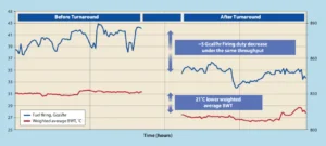
Figure 5 – weighted average BWT and fuel firing before and after Cetek coating
The initial full data set was collected before the turnaround and compared with data after application.
Process data (see Table 1) shows that the application has improved radiant efficiencies and debottlenecked the fired heater limitations. The Cetek coating application has accomplished the objectives of increasing fired heater efficiency and protecting process tubes from corrosion and oxidation, thereby prolonging tube service life.
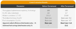
Table 1 – Full Fired Heater Optimization Results
This project has provided an immediate economic benefit and long term reliability for the refinery. It has achieved 13.2% of fuel savings under the same production or a corresponding production increase under the same fuel firing potential. Based on the fuel consumption reduction, the estimated CO₂ savings are circa 9,600 MTPA accompanied by thermal NOx emissions reduction due to lower radiant box temperatures.
The benefit (in Gcal/hr fuel savings) is very similar to the benefit after other independent modifications (see Table 2).
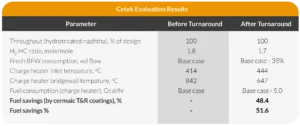
Table 2
Apart from the benefit of the radiant efficiency increase (fuel savings or capacity increase potential), the process tubes will be protected from corrosion and oxidation, thus extending the tube lifetime, and achieving reliability targets.
It is expected that the rapid scale/oxidation trend that occurs in heater process tubes after conventional sand blasting will not be observed during the next two planned maintenance periods after the application, so it will not cause any production (feed rate or RON) bottlenecks. Moreover, the next planned maintenance is expected to be shorter, minimizing downtown and turnaround costs since tube abrasive sandblasting is not needed.
With the application of the high emissivity coating on the fired heaters, the environmentally friendly approach of the refinery and IGS has also been fulfilled. This approach can be expressed in the project’s impact on GHG emissions and the energy intensity index (Ell).
The project allowed the refinery to decrease fuel consumption by 4.7 Gcal/hr while keeping the same conditions for the rest of the unit. This change reflected a CO2 gas emission drop of 9,600 MTPA. Regarding Ell, an improvement of 0.31 was reported after the application (see Table 3).
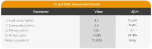
Table 3
The application of Cetek coatings brought an immediate radiant efficiency gain, as expected since a post-project analysis corresponded with a pre-project technical evaluation.
Fifteen months after the project, the fired heater was revisited by Cetek experts. The coating had no defects, continued to perform as planned and bridgewall temperature stayed at the same level.
The refinery has an option to save fuel and the throughput increase option might be considered during high-demand periods. As with all Cetek applications, the unit’s performance will be followed for the life of the coatings, and IGS engineers will undertake IR thermography inspections at regular intervals.

Related Case Studies:
Related Questions:
Other Cetek Services:
CATEGORIES: