Downstream fired heaters is one of the largest cost items in Refining. They consume large amounts of energy to provide the required heat for the process. Improving fired heater performance immediately results in significant payback, greenhouse emission reduction and higher process flexibility. This case study is based on a Catalytic Reformer project. In our 40-years history, we helped to improve performance of many different heaters in downstream refining, syngas and chemical production.
IGS provided PTTGC, Thailand, with an engineering study and CETEK coating application in their CCR Platforming Heaters. Upon completion of the successful field application, once back in service, the results exceeded expectations and provided an excellent payback over the lifetime of the coating.
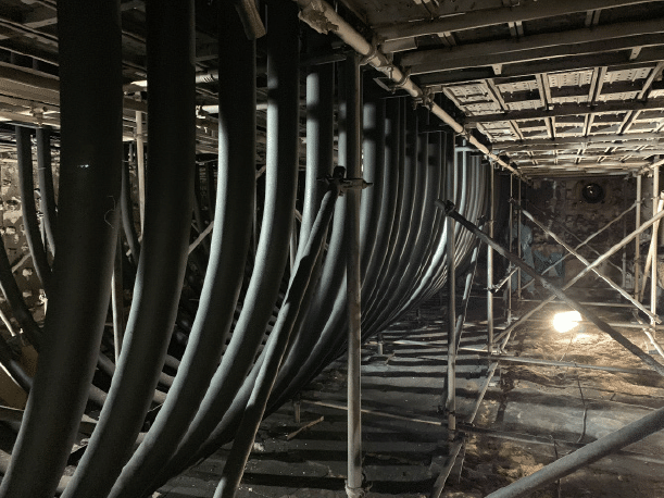
The fired heater optimized in the course of the project is a 27,900 BPD, 4-cell catalytic reformer located in Rayong, Thailand. Each heater has wicket style radiant tube configuration. The metallurgy of the radiant tubes is ASTM A335 P9; 9%Cr, 1%Mo. The refractory lining is ceramic fiber walls and roof with brick floors. The fuel is gas. The initial evaluation required an IR thermography inspection and corresponding operating data from the time of the inspection. Design specifications and general arrangement drawings provided the necessary physical and dimensional data to complete the study.
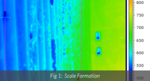
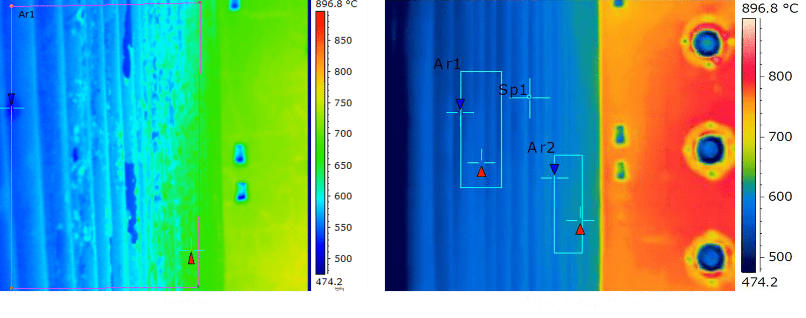
The sample IR inspection image shown in Fig.1 provides an insight into the degree of scale formation and the surface temperature of the scale. As evident in the image, heavy scale presence was hindering heat transfer within the radiant section, thus limiting the fired heater performance.
To overcome the scale, the heater was fired harder leading to fuel wastage and excess emissions. Since natural gas prices are relatively high in this region, this was not a favorable situation and the plant was looking for a solution.
The result of the Cetek engineering study was a recommendation that Cetek high emissivity coatings should be considered for both tubes and refractory surfaces in all four cells. The calculated benefit showed that the improvement in radiant heat transfer efficiency would provide a significant absorbed duty improvement or firing duty reduction, with a generous return on investment over the anticipated life of the ceramic coatings.
As a result, PTGC have decided to go ahead with the CETEK coating application and plans were put in motion.
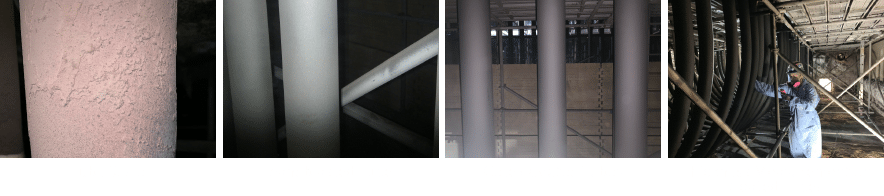
After evaluating the fired heater, IGS also provides turn-key project execution. Coating application requires strict attention to surface preparation and protection of areas of the fired heaters where necessary. The 9%Cr process tubes were grit blasted with a proprietary surface profile, required by the ceramic coating. In order to maintain the blast quality, ambient humidity inside the heaters was controlled.
Cetek high emissivity ceramic coating was applied to the process tubes, ceramic fiber surfaces and the brick.
The application of CETEK coatings in this heater proved exceptionally beneficial to PTTGC. Whether utilizing the fuel savings or production increase benefit, the payback to PTTGC was superbly quick. The approximate 11% benefit was in line with Cetek engineering study, and higher than our historical average of around 7% efficiency improvement in downstream refining fired heaters.
IR thermography analysis from before (left) and after (right) the application is shown below. The heavy scale present before is evident. Clean surfaces observed one year after the coating application prove sustainability of the fired heater performance gain . This was calculated to provide a quick payout and considerable ROI over the expected life of the coating.
Capacity Increase
Fuel Savings

Related Case Studies:
Related Questions:
Other Cetek Services:
CATEGORIES: