4.9% radiant efficiency gain
Efficiency enhancement from 40.3% to 42.3%
Payback within 3 months
Hydrogen production rate increased from 108 to 116 (knm3/h)
Steam reforming is the key process in the formation of syngas for ammonia, methanol, hydrogen and HyCO production. The reformer is the largest and most expensive piece of equipment for these plants, and efficient and reliable operation is key to the performance of the whole plant.
Despite the variety of available commercial hydrogen production technologies like partial oxidation, auto thermal reforming, biomass gasification, and alkaline electrolyzing [1], steam methane reforming of hydrocarbons with a total efficiency of 70-85% [2] remains the most widespread technology worldwide.
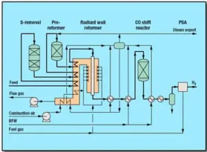
Figure 1 – Typical Refinery Hydrogen Production Unit Process Flow Diagram [3]
Refineries produce hydrogen from hydrocarbon feedstocks such as natural gas, LPG, butane, naphtha, refinery off-gases, etc., using Steam Methane Reformer (SMR) technology. Plant capacities usually range from 5,000 nm3/h to more than 300,000 nm3/h hydrogen, and hydrogen purity can reach up to 99.99%.
The SMR-based hydrogen plant is tailor-made to suit the customer’s needs concerning economics, feedstock flexibility and steam export. In a typical SMR-based hydrogen plant, a mix of hydrocarbon feedstocks or a single feedstock stream is first desulfurized. Subsequently, process steam is added, and the mixture is fed to a prereformer. The prereformer allows the use of a variety of feedstocks, so the primary reformer inlet will be a mixture of CH4, CO, CO2 and H2O.
Further reforming is carried out in the radiant wall SMR. The process gas is reacted in a medium-temperature CO shift reactor and purified by pressure swing absorption (PSA) to obtain product-grade hydrogen. PSA off-gases are used as fuel in the SMR. Excess heat in the plant is efficiently used for process heating and steam generation.
The radiant wall SMR is the heart of this hydrogen plant, consuming sizeable amounts of energy and requiring cutting-edge technologies, such as combustion management, radiant coil design, metallurgy, control, and refractory systems.
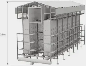
Figure 2 – Traditional Side-Fired Primary Reformer [4]
As process gas progresses through the reforming tubes, the equilibrium position is constantly changing due to the changing gas composition and temperature. At the top of the tubes, the reaction rate is slow due to the low temperature. There is a high heat flux due to the position of the flames and the effect of radiant heat transfer, and the large temperature differential between flue gas and process gas. This corresponds to a wide approach to equilibrium (ATE) at the top of the tubes.
Further down the tubes, there is a fast reaction rate due to the high process gas temperature. Towards the end of the tube, the heat flux is lower, and the rate at which the equilibrium position is changing decreases. It should be noted that at this point in the tube, there is a small temperature differential between the flue gas and process gas and at this point, the reaction rate is controlled by the rate of heat transfer and equilibrium. Therefore, it is possible to achieve a narrow ATE at the bottom of the tubes.
The radiant wall SMR operates at high outlet temperatures up to 900°C with a low steam-to-carbon ratio (typically 2.0-3.0). Advanced steam reforming uses high outlet temperature and low steam-to-carbon ratio, necessary for high energy efficiency and low hydrogen production costs. The reforming process is endothermic, and in a standard box furnace steam reformer, the reformer tubes are heated by burners together with radiant heat from the furnace walls.
IGS offers a free-of-charge heater evaluation for all product lines and services, so any possible changes in the radiant and convection sections are studied and reported before the client or IGS commits to a project [5]. Typical approved IGS services in steam methane reformers (Cetek high emissivity refractory coatings and Tube Tech robotic convection section cleaning) show benefits (as energy savings or production increase) ranging from 1.5% to 5.0% with bridgewall/stack temperature reductions up to 60 °C.
For the evaluations, IGS uses the abovementioned concept of ATE and methane slip as a catalyst performance indicator. Data on methane slip is a part of our data questionnaire system to address catalyst behaviour while performing radiant duty calculations. Therefore, for the generic case, radiant duty is a function of feed flow rate and composition, prereformer operating conditions (if applicable), S/C ratio, inlet/outlet temperatures and pressures, as well as ATE.
A twin-cell (also called by Licensor «Duplex») side-fired primary hydrogen reformer in Southern Europe suffered from high bridgewall (arch) temperature after reaching a production of ca. 110 knm3/hr because it was frequently passing a bridgewall temperature alarm set to 1100 °C. This limiting factor severely restricted not only hydrogen production unit performance but also downstream hydrocracking and hydrotreating units. This issue couldn’t be resolved with combustion adjustment and redistributing higher heat release close to the bottom section due to the tube metal temperature limit due to the radiant tube metallurgy.
Since energy interacts with the refractory walls of the heater radiant section, an emissivity upgrade has become a legitimate path towards energy efficiency enhancement or debottlenecking as required. Therefore, to continue operating at a higher capacity, which was dictated by the market situation, the licensor issued a specification for tubular reformer high emissivity refractory coating to debottleneck this hydrogen production unit, allowing an additional 5% of hydrogen production rate without reaching the abovementioned limitations.

Figure 3 – High Emissivity Refractory Coatings applied to 3 different refractory materials
IGS Cetek high emissivity refractory coatings were applied to all radiant surfaces (burner tiles, insulating brick around tiles and ceramic fibre in the top section) by IGS operations teams within only a five-day timeframe, a turnkey project delivered on time and on budget (Figure 3). Measurements were taken before and after the coating application from the second platform level using every fourth inspection port. The results clearly indicated the increase in emissivity from 0.34 to 0.92, allowing additional hydrogen production (Figure 4) without approaching bridgewall temperature threshold limits.
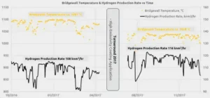
Figure 4 – Post-Job Data Analysis under similar operating conditions
To continue operating this unit at the highest possible capacity, even with an extended turnaround cycle from 3 to 4 years, after IGS and the client process team re-evaluation, it was decided to reapply the high emissivity refractory coating during the 2023 turnaround. The life of the IGS Cetek system, when applied to refractory surfaces is related to the temperature to which it is subjected and the local environment.
Typically, the coatings will gradually lose emissivity in steam methane reformers, declining from over 0.92 to around 0.7-0.8 after approximately six to eight years. This is still substantially higher than the original, uncoated refractory. At this stage, it is highly recommended to touch up the coatings to boost the emissivity to the original level and restore performance. The deterioration is caused by high temperature and solid-state diffusion of the elements in the coating, which provide the high emissivity properties. The rate of deterioration may be increased by high localized heat release around burner tiles.
The highest reported bridgewall (arch) temperature throughout the six-year run following the initial application in 2017 was only 1055 °C under more than 110 knm3/hr hydrogen production rate, which is a clear indicator of the coating’s longevity and reliability. Bridgewall temperatures demonstrated a stable, well below an alarm threshold behaviour, fully alleviating the initial plant bottleneck limitations (Figure 5).

Figure 5 – Bridgewall (Arch) Temperature Trend 2016-2023
Projects executed during the 2017 and 2023 turnaround provided an immediate payback and flexibility in operation for the client. Furnace performance evaluation revealed a sizeable apparent radiant efficiency enhancement (40.3% to 42.3%) with a corresponding bridgewall temperature reduction of more than 50°C. This enhancement was utilized to increase the hydrocracking unit’s capacity, resulting in an additional production margin of ca. €4.8M per year. Less fuel firing is required to produce relatively the same amount of hydrogen with an equivalent of 18400 MTPA CO2 emission reduction due to a 4.9% radiant efficiency gain. Achieved radiant efficiency enhancement may be utilised not only to reduce fuel consumption with CO2 emissions reduction but also to increase throughput/severity under the same firing rate. A detailed analysis is shown in Table 1, including the 2023 reapplication.

Table 1 – Final Primary Reformer Efficiency Analysis
The IGS Cetek application brought an immediate radiant efficiency gain, as predicted and a post-project analysis corresponded with the pre-project technical evaluation. The refinery, apart from debottlenecking and refractory encapsulation, has the option to save fuel or to increase throughput under the same firing rate during high-demand periods. As with all IGS Cetek applications, the unit’s performance will be closely followed for the lifetime of the applied coating systems [6].

Related Case Studies:
Related Questions:
Other Cetek Services:
CATEGORIES: