When planning a practical, functional, and cost-effective revamp, treating vacuum unit heater-inlet-through-ejector-outlet (Figure 1, [1]) as a single system is essential. Nonetheless, process flow sheet models frequently fail to accurately depict the operation or address the numerous non-ideal conditions in a refinery vacuum unit. Under these circumstances, mistakes in calculating process stream data can lead to reduced operational durations, increased heat flux zones, tube coking and low gasoil yields.
A major challenge in processing crude feedstocks, particularly those derived from heavy alternative sources like bitumen, is tube coking. Coking, the formation of solid carbon deposits, is influenced by factors such as high temperatures, prolonged residence time, low flow velocities, and the diverse composition of the feedstock.
The buildup of coke within the tubes not only reduces heat transfer efficiency but also restricts flow, leading to increased pressure drop and potentially costly downtime for cleaning and maintenance. Therefore, mitigating tube coking is crucial for maintaining operational efficiency and profitability in refineries processing heavy feedstocks.
One example is how phase separation in the outlet vacuum heater tubes and transfer line affects the predicted heater outlet temperature and the estimated liquid flow rates in the wash section. Neglecting to consider phase separation in these lines can reduce the yield of gasoil products and lead to an excessively low flow rate of wash oil in the column. More critically, if this phenomenon occurs in the heater outlet tubes, it may cause tube overheating in vapour-only regions with low heat transfer coefficient, causing the actual tube metal temperature to approach the design metal temperature. For this scenario is not only a question of underestimating wash rate and overestimating gasoil yield, but safety.
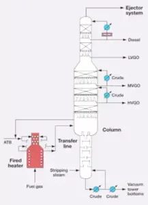
Figure 1 – Single System: Heater Inlet Through Ejector
Most conventional modelling practices assume liquid and vapour equilibrium at the vacuum heater outlet even for these large-diameter horizontal tubes. Still, in reality (especially after lowering the initial vacuum column pressure), liquid and vapour phases tend to separate even before entering the transfer line.
Calculated phase regimes are either stratified or stratified wavy. Stratified phases cause the liquid and vapour to have poor mass and energy exchange across the interface, resulting in poor liquid and vapour contact [2]. Thus, phase separation causes the vapour to flow through the top of the horizontal portion of roof tubes, and this vapour becomes superheated due to pressure reduction. The result of the roof tube overheating is shown in Figure 2. The upper part of the tubes doesn’t see a flame, so it is not subject to any significant oxidation scale formation. Keeping that in mind, the sizeable gap between the actual process outlet temperature and tube metal temperature (>200 °C) can be encountered, way exceeding the best design practices of no more than 80 °C or a maximum TMT of 500 °C [3-5].
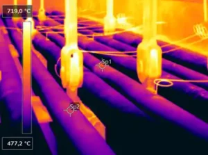
Figure 2 – Vacuum Heater Infrared Inspection: Sp1: 619 °C; Sp2: 592 °C.
An energy company contacted the IGS thermal efficiency team to design a solution to tackle the tube coking issue since numerous attempts to adjust the operational regime had no success. The internal investigations also didn’t result in any solution that would avoid costly revamps during the upcoming shutdown.
The large OD of the outlet roof tubes (Figure 3) within the vacuum heater outlet tubes reduced mass velocity, resulting in liquid and gas phase separation. This caused hot spots due to the lower heat transfer coefficient inside the top portion of the roof tubes. IGS recommended that proprietary ceramic wrapping technology be used to cover the 180° circumferential surface of 8” and 10” top roof tubes, along with IGS proprietary technology to secure material on top of the tube surface.
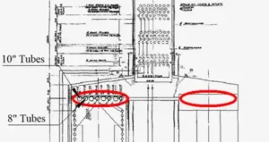
Figure 3 – Coked Vacuum heater Tubes Marked Red.
The objective of this project, according to the IGS evaluation, was to reduce heat flux from approximately 11000 to 1150 Btu/(ft2⋅hr) with a ca. 190oC tube wall temperature drop, entirely removing tube coking hot spots on the top part of these 8” and 10” tubes. The IGS operations team successfully completed all work within the heater over a three-shift period, finishing on time and within budget while prioritizing safety as their foremost principle.
Skin thermocouple readings were also analyzed before and after the project (Figure 4). The expected tube wall temperature reduction was confirmed with the data following the project execution (596 vs 416 °C). At the same time, due to the lowering of the available area for heat transfer (only for the low HTC region), the flue gas temperature entering the convection section increased by only 12 °C on average without the increase in stack temperature.
The coked vacuum heater tubes were debottlenecked without any penalty in terms of efficiency, allowing additional throughput for the vacuum unit and downstream facilities without any TMT-related issues.
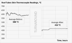
Figure 4 – Roof Tubes Skin Thermocouple Readings Before and After

Related Case Studies:
Related Questions:
Other Cetek Services:
CATEGORIES: