Cetek High Emissivity Coating Stops Oxidation of Radiant Tubes
PROBLEM
Oxidation of external tube surfaces is responsible for metal loss at around 0.25 mm/year, which limits the tube life. Scale growth produces an insulating layer that restricts conductive heat transfer to the process fluid and eventually limits production.
Moreover, severe scaling also prevents accurate on-stream monitoring of tube skin temperatures, using IR thermography. Following a detailed root cause analysis, it was recommended to apply Cetek Ceramic Coating to the radiant tubes. In addition, Cetek High Emissivity Ceramic Coatings were applied to the refractory surfaces to improve radiant heat transfer efficiency.
SOLUTION AND RESULTS
The application of Cetek High Emissivity Ceramic Coatings stopped oxidation. The units are no longer limited and are running at design capacity or above. Payback from the investment was within 6 months.
Ceramic Coating Technology
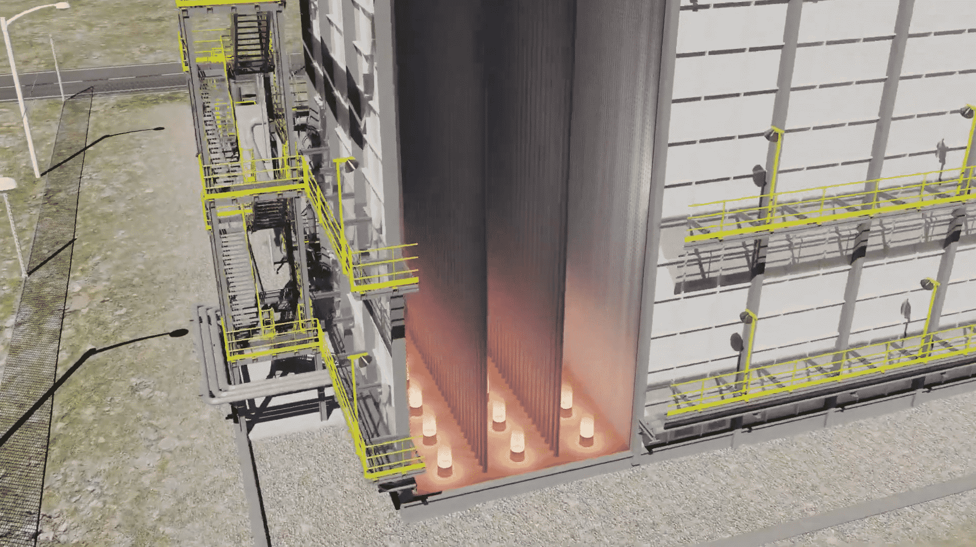
The application of high emissivity ceramic coatings to the refractory and radiant tube surfaces creates a near Black Body enclosure, which maximizes radiant heat transfer efficiency.
In addition, preventing oxidation of radiant tube surfaces eliminates metal loss and extends tube life.
Process | Equipment Design
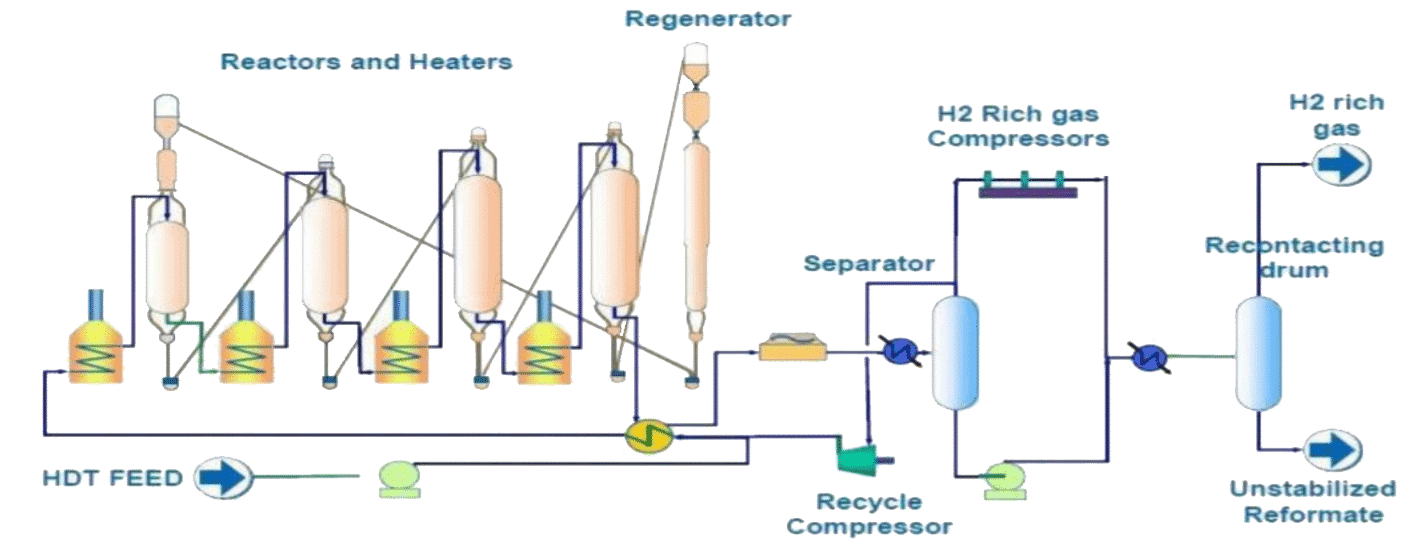
The Aromatics Plant was commissioned in November 2009. It consists of a naphtha reforming unit based on a continuous catalyst regeneration (CCR) system designed to produce aromatics rich stream along with high purity hydrogen as a by-product. The plant typically experiences varied feed composition (higher naphthenic content, etc.) depending upon the quality of imported naphtha.
Low Pressure High Temperature Operation
The high performance of the licensed process is largely owed to low-pressure operation coupled with high temperatures, which, in conventional fixed-bed reactors would lead to very short cycle lengths.
Continuous Regeneration
Continuous regeneration eliminates the need for a shutdown for the regeneration of the earlier fixed bed reformers. It also minimizes the amount of catalyst in the unit, while allowing high aromatics yield and quality. A high temperature (in the range of 545°C) is required to promote the chemical reactions which improve aromatics production. Hence the need for reheating of the feed.
Arbor Type Fired Heaters
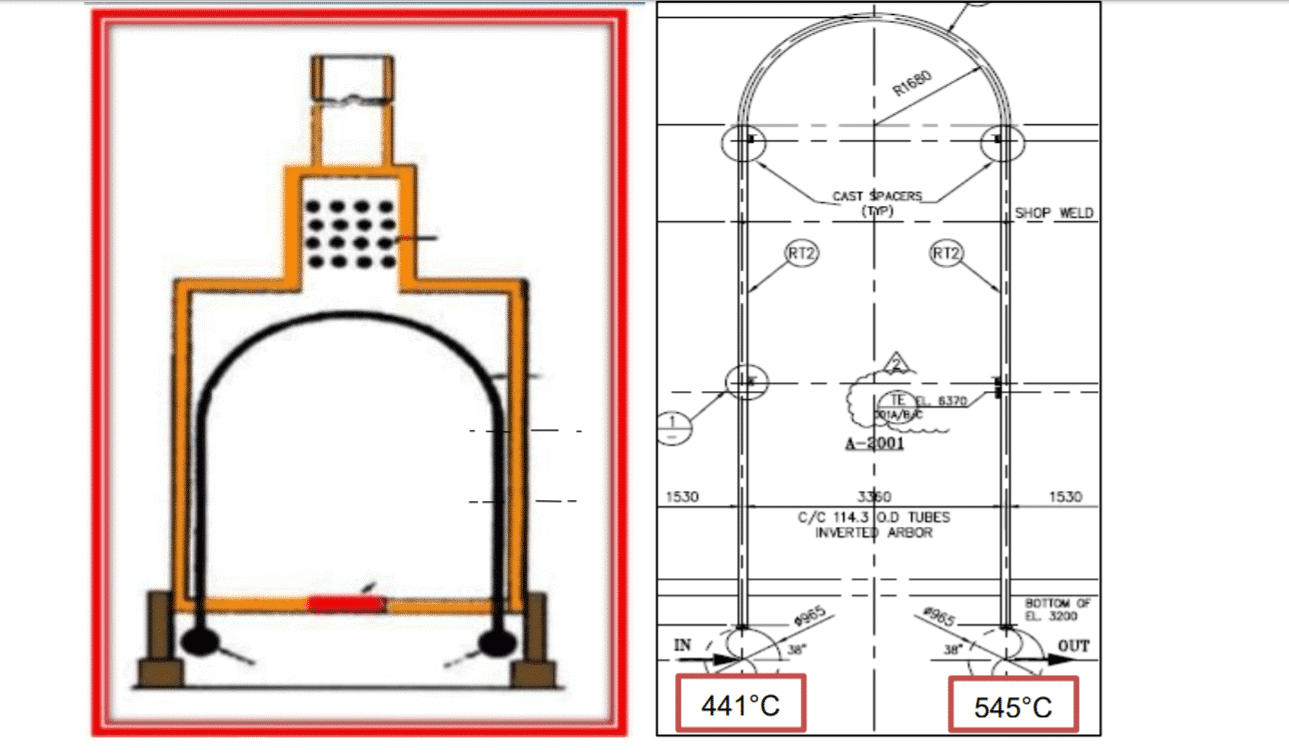
For this purpose, 4 heaters are provided (1 preheater and 3 inter heaters) with their primary purpose to provide the required heat for reactions in reactors. The heaters are arbor type with vertical inverted “U” type radiant tubes (Figure 5), which are typically used for low pressure all vapor flow units like CCR. The single-pass radiant tubes have a material specification of ASTM 335 Gr P9 (9Cr-1Mo) with dimensions of OD 114.3 x 6.02 mm wall thickness and corrosion allowance of 1.5 mm. Heaters are designed as per API (2) 530 with a design life of 100,000 Hours.
Damage Mechanisms
The life of radiant tubes in furnaces is governed by the combination of several possible time-dependent degradation mechanisms and by the tube wall temperatures and loading. The main degradation mechanisms in reforming service are fireside oxidation, thermal microstructural degradation, and creep. Apart from this, carburization and metal dusting have also been reported in many catalytic reforming heater tubes, although not very common because of sulfide injection that forms a protective layer and prevents carbon diffusion.
Process Tube Materials
Tube materials in CCR fired heaters are usually 9Cr-1Mo. Tube dimension design and corrosion allowance generally follow API 530 standard. With time, these Cr-Mo materials experience thermal degradation, and their typical normalized and tempered structure (pearlite or bainite depending upon normalization heat treatment) and ferrite grains will degenerate to ferrite grains with intra- and intergranular carbides. The material’s tensile and creep strength reduce during this process.
Oxidation
Severe scaling due to oxidation is expected in these heaters due to high operating temperatures. Above approximately 500 °C, the 9Cr-1Mo materials tend to oxidize and may scale very rapidly as temperatures increase. The corrosion rate based on material and temperature is around 0.25mm/year.
Carburization
It is the diffusion of carbon into the metal matrix at high temperatures >600°C forming a hard and brittle structure. The extent of carburization can be determined by metallography and causes a substantial increase in hardness and loss in ductility. Where the operating temperatures result in high metal temperatures of about 650°C or higher, carbon at the surface has a higher tendency to diffuse into the metal and thicker carburized layers tend to form. This phenomenon initially strengthens the tube wall, but ultimately leads to crack initiation, through-wall crack propagation, and thus enhanced rates of life consumption.
Metal Dusting
It is a catastrophic form of carburization in the 480°C to 816°C temperature range. Generally, results in rapid metal wastage in the form of erosion at the hotter areas of the tubes or small pits filled with metal oxides and carbides. In mild form, metal dusting results in discrete pitting, but at an extreme, can effectively produce a rapid inner wall thinning mechanism.
Creep
Other prominent damage mechanisms include Creep and its susceptibility increases with increasing temperature and reduced thickness. In subject heaters, to date, only external oxidation has been found, and no internal carburization or metal dusting or signs of creep damage have been detected.
Aromatics Plants | Petrochemical Unit
The aromatics plant is an important downstream petrochemical unit that produces various aromatic hydrocarbons such as xylenes, benzene, and toluene, which are the basic building blocks for the production of polyester and polymers resulting in different consumer goods.
The heart of the aromatics plant is a licensed high-performance Naphtha Reforming unit that operates at low pressure and high temperatures required to promote chemical reactions that improve aromatics production.
Fired Heaters | Arbor Type Coil Configuration
To achieve the required heat, there are four fired heaters with arbor type coil configuration that raise the feed naphtha temperature to around 545°C. The radiant tubes of the heaters are of 9Cr-1Mo (ASTM(1) A335 Gr P9) metallurgy with a maximum tube wall temperature of 652°C. The tubes are prone to excessive scaling due to high-temperature oxidation and scale thickness of up to 1-2mm were found in the tubes. The problem arising due to scaling affects not only the mechanical integrity of the radiant tubes but also leads to multiple operational constraints.
Oxidation and Scale Growth
Oxidation of external tube surfaces is responsible for metal loss at around 0.25 mm/year, which limits the tube life. Scale growth produces an insulating layer that restricts conductive heat transfer to the process fluid and eventually limits production.
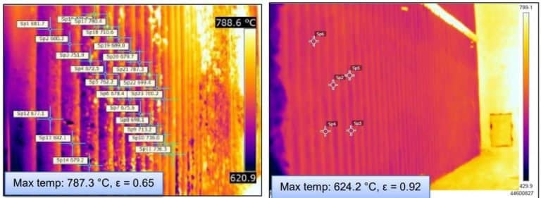
Moreover, severe scaling also prevents accurate on-stream monitoring of tube skin temperatures, using IR thermography.
Root Cause Analysis
Following a detailed root cause analysis, it was recommended to apply a ceramic coating on the radiant tube and extend it to refractory in the furnace box to improve operational and thermal efficiency, while maintaining metallurgical integrity and reliability.
Observations
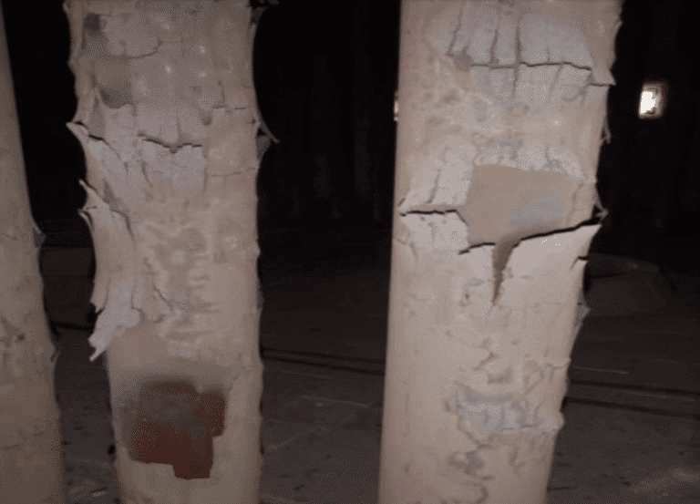
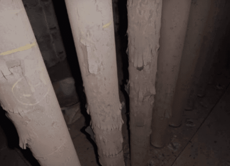
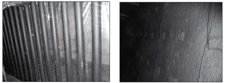
- Severe scaling on the external surface of the radiant tubes with thick scales (tree bark appearance) more prevalent in the outlet tubes of the heater (Figure 1)
- Scaling was due to oxidation, which is common in these heaters considering the high operating and tube wall temperatures (Figure 2).
- Scale thickness measured were in the range of average 0.5-1 mm, with some locations as high as 2 mm.
- By appearance, it typically looked like two layers of oxide scales generated out of the tube metal. Loose scales fell on the furnace floor, whereas, some tight adherent scale was still found on the tube surface.
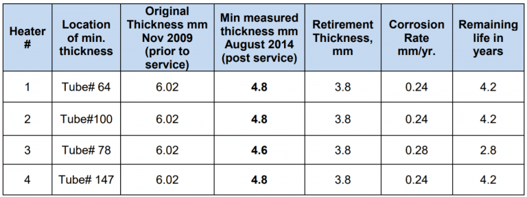
- UT measurements (spot + scanning) were done across many tubes of the 4 heaters, and a minimum thickness of 4.6 mm was recorded as against the original thickness of 6 mm.
- Overall review of thickness measurements for all heaters reveals a minimum of 1 mm reduction in most of the radiant tubes.
- The corrosion rate was calculated based on the lowest thickness recorded and is 0.28 mm/year.
- Based on the minimum recorded thickness for each heater, the corrosion rate was calculated to determine the remaining life of the tubes (Table below). The corrosion rate was based on the operating life of 5 years from Nov 2009 – August 2014.
Ceramic Coating Technology
The application of high emissivity ceramic coatings to the refractory and radiant tube surfaces creates a near Black Body enclosure, which maximizes radiant heat transfer efficiency. In addition, preventing oxidation of radiant tube surfaces eliminates metal loss and extends tube life.
Increased Throughput
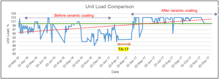
The unit is being operated at higher throughput irrespective of feed variations. The unit load prior to ceramic coating was around 97-98%. Moreover, when processing high naphthenic feed, the unit load was reduced further to 96%. However, post coating, unit is being operated at 103% irrespective of feed composition, and even with high naphthenic feed, the desired throughput is obtained with the same fuel firing.
Controlled Steam Generation
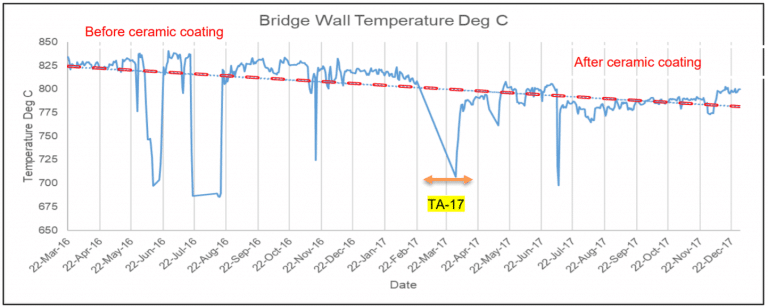
With ceramic coating on tubes and refractory, radiant heat loss has considerably reduced, resulting in increasing the efficiency of the radiant heat transfer and reducing bridge wall temperatures by average 30-50 °C. Hence, even with operating at higher loads, the arch temperatures have relatively reduced, avoiding excessive steam generation and high heat loads on the convection steam coils.
Fuel Gas Savings
With the commissioning of a new refinery, the hydrogen-rich fuel gas from the aromatics plant is being sent to the Off-Gas recovery section, and the heaters are being operated entirely on natural gas. The amount of fuel burnt in MMBTU/hr post-coating to maintain a 103% load is less than the fuel required to maintain a 96-99% load prior to coating.
Cost Savings & Return on Investment
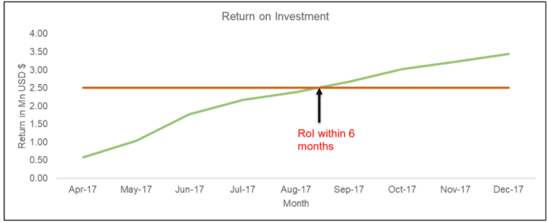
The total project cost was around 2.5 million USD, with an expected Return on Investment (ROI) within 11 months of operation with an Internal Return Rate (IRR) of 111%. However, considering all factors and favorable market, the ROI was achieved within 6 months of operation. Table 6 below provides the cost benefits realized due to operating at higher unit loads and fuel gas savings.
Cetek Coating Advantages
- Eliminates oxide scale formation and increases conductive heat transfer to the process fluid.
- High emissivity coating of the refractory increases radiant heat transfer efficiency.
- The increase in radiant section efficiency allows for energy (fuel) savings and/or production increase, while providing uniform heat distribution in the firebox.
- Limits foulant adhesion to the tube surface.
- Lowers bridge wall temperature and convection section temperatures.
- Allows tube wall temperature to be directly inferred from thermography or infrared measurement.
Related Questions:
Free consultation with an IGS Subject Matter Expert
IGS is here to provide information, answer questions and create an effective solution for your needs.

