
Rectifying Failed Thermal Spray Corrosion Protection
Problem
A US refinery identified a problem with its second stage desalter and overhead accumulator vessels during a routine inspection.
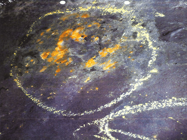
A nickel-copper thermal spray coating had been applied in both of these vessels approximately 20 years ago. Initially, the coating performed as expected, however, after some time, localized damage was evident on the bottom third of both vessels.
Organic Coating Patch Repairs
Initially, various organic coatings were chosen for patch repairs to the bottom of the shell. These coatings needed to be applied repeatedly every 4-5 years.
In 2014, the inspection revealed areas where both the historical nickel-copper thermal spray coating and organic patch repairs have worn away completely, leading to deep pitting and metal wastage beyond the existing corrosion allowance

Evaluation of Alternatives – Organic Coatings, Weld Overlay, Thermal Spray
Organic coatings, weld overlay, and high velocity thermal spray were evaluated as potential options by the refinery. As the refinery favored a solution that could remain maintenance-free for longer than 4-5 years, only high velocity thermal spray and weld overlay were still being considered. IGS presented evidence differentiating HVTS and “low velocity” thermal spray, which was previously applied in these vessels.
Thermal Spray Coating Failures
Typical Thermal Spray coatings are not suitable for internal protection of mission critical process equipment due to their permeability, weaker bond strength and propensity to cracking. These “low velocity” thermal spray systems cannot produce flat and tightly-packed particle sizes or nano-scale grain structures, leading to the coating’s failure due to corrosion and/ or permeation.
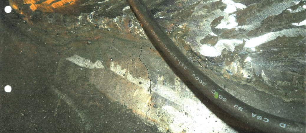
Weld Repairs – Crack on a HAZ
Moreover, when weld repairs were attempted, adjacent to the failing thermal spray, a crack had formed on its heat affected zone (HAZ). In 2017, refinery engineers decided they needed a more permanent solution.
H3 Permeation
In addition, low velocity thermal spray materials’ cladding particles form surface oxides in flight. These oxides then form part of the applied thermal spray structure and are permeable, creating a pathway for corrosive media to penetrate through the coating. Permeability leads to subsequent substrate corrosion and premature thermal spray failure.
H3 Stress
Moreover, being applied at high thicknesses, thermal spray structures are inherently highly stressed. Such highly stressed coatings have a high propensity to crack and subsequently fail in service.

HVTS Solution
IGS proposed a High Velocity Thermal Spray (HVTS) alloy cladding solution to stop corrosion for the expected life of the asset without any further maintenance anticipated for at least the next 15+ years.
HVTS technology utilizes next generation alloy materials, which offer erosion-corrosion protection, even in high-temperature and high-pressure service up to 1371°C/2500°F.
HVTS also offered significant time savings compared with weld overlay. As a result, the refinery project manager welcomed this proposal, and HVTS work was scheduled for the Spring of 2019.
Application
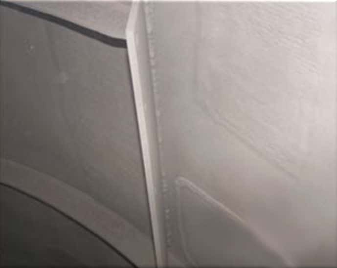
IGS started by clean blasting each unit, allowing the refinery’s QC to inspect and address any issues with the vessels’ substrate. The Overhead Accumulator required no mechanical work, whereas the Second Stage Desalter required welding repairs attributable to the deep pitting that occurred due to the poor quality of the previously applied coating.
Completed Application
HVTS application was completed on time and within schedule, even accounting for unexpected delays. The bottom third of the overhead accumulator, including the stem pipe with a vortex breaker and a flange, were protected with HVTS.
On the second stage desalter, HVTS was applied to the 5 O’clock to the 7 O’clock position of the vessel and the manway.
Inspection
Final inspection of the work scope involved the generation of a cladding thickness record with mapped electromagnetic stand-off gauge (MLO) readings on a defined reference grid across the area protected.
This record will be used for future inspection and verification of cladding’s integrity.
HVTS cladding systems can be readily inspected visually for any signs of deterioration and thickness measurements taken with a magnetic liftoff gauge.
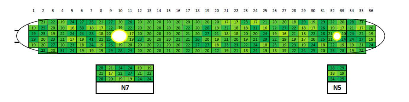
Overhead accumulator HVTS thickness measurement
IGS has invested heavily in the development and optimization of its High Velocity Thermal Spray (HVTS) process technology, materials technology, application procedures and field personnel capability.
Decades of successful cladding applications coupled with fast mobilization and turnkey applications are helping position IGS as a go-to service provider for the Oil, Gas and Petrochemical sites worldwide.
Free consultation with an IGS Subject Matter Expert
IGS is here to provide information, answer questions and create an effective solution for your needs.