
TubeTech™ Reinstates Heat Transfer Efficiency of an Ethylene Furnace
Heat Transfer Efficiency Results for the Steam Cracker
The plant reported a two percentage points increase in overall fuel efficiency from 89.5 to 91.5 on average leading to 2 MW fewer combustion losses. The plant has reported a payback period of less than four months. A 40 °C drop in the previously high stack temperature was achieved by reinstating convection section heat transfer efficiency.
Convection Section Fouling
Over the last six years in operation, the stack temperature became higher – rising from 190 °C to 230 °C, equaling 2.0% losses in fuel efficiency. The furnace had no access points for cleaning.
No-Man-Entry Convection Section Defouling
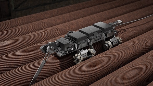
To perform effective heat transfer restoration using a unique Remotely Operated Vehicle (ROV) fouling removal technology and protect the existing equipment from water exposure, the following three steps have been implemented:
1. New access openings were created to enable placing an ROV on top of each convection bundle.
2. The radiant box has been isolated.
3. All effluent and debris after fouling removal have been collected and displaced to the ground level in sediment containers.
Key Benefits
The ROV technology entirely removed fouling from the convection bank coils. The system removed 90%+ of fouling from all convection bundles.
No refractory was damaged since ROVs are programmed to direct a high-pressure medium to the tubes only. All activities were done in 4×12-hour shifts.
A 40 °C drop in stack temperature was achieved. The plant reported a two percentage points increase in overall fuel and a payback period of fewer than four months.
Ethylene Furnaces
Ethylene and propylene are precursors to many chemicals, fibers, and plastics that are used in our day-to-day life. At most petrochemical sites, the ethylene or pyrolysis plant is the mother unit that feeds downstream units. The heart of the ethylene plant is a system of specially designed furnaces where thermal cracking processes are conducted.
These ethylene furnaces are complex pieces of equipment and consume significant energy resources, requiring maintenance and operator’s attention due to the possibility of coke formation inside radiant tubes.
Frequently shutting down furnaces for decoking or maintenance costs money, disrupts downstream sections, and prevents the plant from meeting its production targets.
Steam cracking, or pyrolysis, is a complex, non-catalytic process that involves numerous reactions, intermediate species, and final products. The reactions are highly endothermic, so heat is needed to initiate and sustain them. The cracked gas is a mixture of components that includes hydrogen, methane, olefins (e.g., ethylene, propylene, butylene as target products), diolefins, acetylenes, naphthenes, aromatics (benzene, toluene, xylenes) and tars.
Four main operational parameters determine the target ethylene and propylene yields on the existing facility: coil outlet temperature (usually between 820 °C and 870 °C), hydrocarbon partial pressures (low pressure favors selectivity towards ethylene/propylene), residence time (short RT favors selectivity), and the distribution of heat flux in the radiant
section (lower and uniformed heat flux favors run length, usually 800-1800 hours).
The designed balance of absorbed duty in the convection section (c/s) and the radiant section (r/s) is adversely affected by the fouling of the external tube surfaces in the c/s.
Fouling leads to a lower r/s inlet temperature and the need to increase radiant section heat flux to maintain production. A higher r/s heat flux produces an increased coke deposition rate inside the radiant tubes and a shorter run length.
Steam Cracking Unit Description
A cracking furnace functionally is divided into three zones: radiant section, convection section, and transfer line exchangers (TLEs). TLEs are placed vertically, with cracked gas in the inner pipe (tube side) and boiler water/ steam in the outer pipe (shell side). TLEs are waste heat boilers (WHB) placed at the outlet of the radiant coils to rapidly reduce the cracked gas temperature to mitigate secondary reactions by producing saturated VHP steam.
Radiant Section
The firebox is a rectangular, refractory-lined volume within which the radiant coils are suspended vertically, firing from the bottom. The radiant coil, in this case, is SRT type (short residence time), favoring selectivity towards ethylene production. Two fireboxes have a common convection section, so the performance of the convection section influences two radiant chambers at the same time.
Convection Section
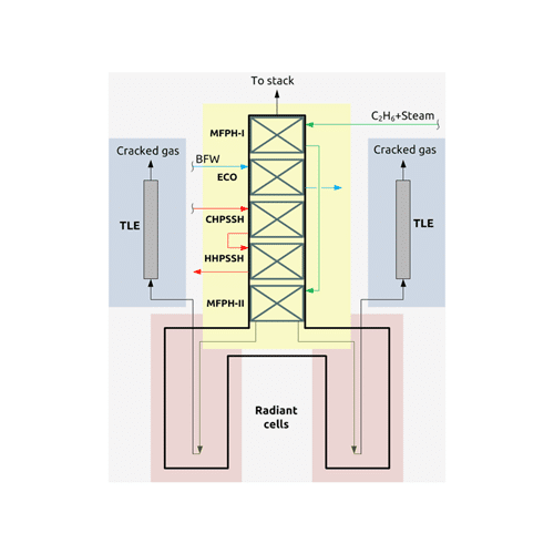
The convection section is located above two fireboxes. The services of the different heat transfer banks shown in figure 1 include:
- Mixed Feed Preheater (MFPH-I);
- Economizer (ECO);
- Cold High-Pressure Steam Superheater (CHPSSH);
- Hot High-Pressure Steam Superheater (HHPSSH);
- Mixed Feed Preheater (MFPH-II).
Heat Transfer Restoration
Over the last six years in operation before cleaning, the stack temperature rose from 190 °C to 230 °C, equaling 2.0% losses in fuel efficiency.
The purpose of this project was to reinstate the overall fuel efficiency, save fuel and cut emissions. Unfortunately, windows in the convection section were not designed to provide access to any type of fouling removal equipment
Acknowledgments and New Data Two Years After Cleaning
Heat distribution between c/s and r/s is crucial in coking-sensitive services. Keeping the convection section surface clean helps save fuel and increases steam generation and positively influences the steam cracking process. The achieved benefit was cca. 16 000 MWh/year fuel savings and 2500 tons annual CO2 reduction (fuel is CH4/H2 mixture). Due to higher crossover temperature (radiant inlet temperature), the residence time will be slightly less, with an additional opportunity to make more ethylene due to enhanced selectivity.
After almost 2 years, in 2022, the client reported a slight elevation in stack temperature of 10 °C and a stable efficiency increase of 1.5 percentage points. The client was happy with the achieved result and has since conducted TubeTech™ defouling as a pre-emptive measure in 2023 in the sister unit and then back to the first unit in 2024.
To make obtained benefit long-lasting, IGS also recommends a combination of the TubeTech™ ROV cleaning with Cetek’s proprietary ceramic refractory coatings to protect and encapsulate the ceramic fiber and stop refractory deterioration and new fouling formation on the outside surface of the convection tubes.
Free consultation with an IGS Subject Matter Expert
IGS is here to provide information, answer questions and create an effective solution for your needs.