
Extending Tube Life and Improving Efficiency in an Aromatics Plant
Executive Summary
A petrochemical aromatics plant faced significant challenges with oxidation and scaling of their radiant tubes, leading to reduced efficiency and shortened tube life. Through the implementation of Cetek® ceramic coating, the plant achieved significant improvements in operational efficiency and tube longevity, demonstrating both technical and financial benefits that exceeded initial projections.
Background
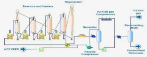
The aromatics plant, commissioned in November 2009, is a crucial downstream petrochemical unit producing essential aromatic hydrocarbons including xylenes, benzene, and toluene. These components serve as fundamental building blocks for polyester and polymer production, contributing to various consumer goods. At the heart of the operation is a sophisticated naphtha reforming unit based on a continuous catalyst regeneration (CCR) system. This system is designed to produce an aromatics-rich stream along with high-purity hydrogen as a valuable by-product.
The plant’s design accommodates varied feed composition, including higher naphthenic content depending on imported naphtha quality. The high performance of the licensed process relies on low-pressure operation coupled with elevated temperatures, a combination that would typically result in very short cycle lengths in conventional fixed-bed reactors. The continuous regeneration system eliminates shutdown requirements for catalyst regeneration while minimizing catalyst quantity and maintaining high aromatics yield and quality.
Process Equipment and Design
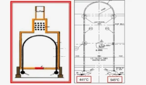
To achieve the required reaction temperatures of approximately 545°C, the plant employs four fired heaters: one preheater and three inter-heaters. These heaters feature an arbor type design with vertical inverted “U” type radiant tubes, specifically chosen for their suitability in low-pressure, all-vapor flow units. The single-pass radiant tubes are
constructed from ASTM 335 Gr P9 (9Cr-1Mo) material, with dimensions of 114.3mm OD and 6.02mm wall thickness, including a corrosion allowance of 1.5mm. Following API 530 standards, these heaters were designed for a service life of 100,000 hours.
Damage Mechanisms and Material Degradation
The longevity of radiant tubes in furnaces is determined by several time-dependent degradation mechanisms, primarily influenced by tube wall temperatures and loadings. In reforming service, these tubes face three main challenges: fireside oxidation, thermal microstructural degradation, and creep. While carburization and metal dusting have been documented in many catalytic reforming heater tubes, these issues are less common due to sulfide injection, which creates a protective layer preventing carbon diffusion.
The standard material choice for CCR fired heater tubes is 9Cr-1Mo, with tube dimensions and corrosion allowance following API 530 standards. Over time, these Cr-Mo materials undergo thermal degradation, during which their normalized and tempered structure (pearlite or bainite, depending on normalization heat treatment) and ferrite grains degenerate into ferrite grains with intra- and intergranular carbides. This degradation process progressively reduces the material’s tensile and creep strength.
Common Tube Damage Mechanisms
Oxidation represents the primary concern in these heaters due to high operating temperatures. When temperatures exceed 500°C, 9Cr-1Mo materials become particularly susceptible to oxidation, with scaling rates accelerating as temperatures rise. Under these conditions, the typical corrosion rate reaches approximately 0.25mm/year.
Carburization occurs when carbon diffuses into the metal matrix at temperatures above 600°C, resulting in a hard but brittle structure. At metal temperatures of 650°C or higher, carbon more readily diffuses into the metal, forming thicker carburized layers. While this
initially strengthens the tube wall, it ultimately leads to crack initiation and propagation, accelerating the rate of life consumption.
Metal dusting, occurring between 480°C and 816°C, represents a particularly severe form of carburization. This mechanism can cause rapid metal wastage through erosion in hotter tube areas or create small pits containing metal oxides and carbides. In mild cases, it manifests as discrete pitting, but severe cases can lead to rapid inner wall thinning.
Creep susceptibility increases with both temperature and reduced thickness, presenting another potential damage mechanism. However, in the subject heaters, inspections revealed only external oxidation, with no evidence of internal carburization, metal dusting, or creep damage.
Problem Assessment
External tube surface oxidation emerged as a primaryconcern, causing metal loss at approximately 0.25 mm/year and significantly limiting tube life. The resulting scale growth created an insulating layer that restricted conductive heat transfer to the process fluid, ultimately constraining production capacity. Additionally, severe scaling prevented accurate on-stream monitoring of tube skin temperatures using IR thermography.
Detailed inspections revealed several issues:
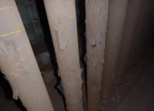
- The external surface of the radiant tubes showed severe scaling with a distinctive tree bark appearance, particularly prominent in the heater’s outlet tubes (Figure 1).
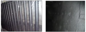
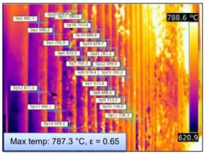
- The observed scaling resulted from oxidation, a common occurrence in these heaters due to
their high operating and tube wall temperatures (Figure 2).

- Scale thickness measurements averaged between 0.5-1mm, with some locations reaching up to 2mm.
- The oxide scale formation presented as two distinct layers generated from the tube metal. Some scales had detached and fallen to the furnace floor, while others remained tightly adherent to the tube surface.
- Ultrasonic testing (UT), including both spot checks and scanning across the four heaters’ tubes, revealed a minimum thickness of 4.6mm compared to the original 6.02mm.
- An overall review of thickness measurements across all heaters showed that most radiant tubes had experienced at least a 1mm reduction in thickness.
- Based on the lowest recorded thickness, the calculated corrosion rate was 0.28mm/year.
- The remaining life of the tubes was determined using corrosion rates calculated from minimum recorded thicknesses for each heater, based on operating data from November 2009 to August 2014 (Table1)
Technical Solution and Cetek® Implementation
Following comprehensive root cause analysis, the team recommended applying Cetek® ceramic coating to both the radiant tubes and refractory surfaces in the furnace box. This solution aimed to improve operational and thermal efficiency while maintaining metallurgical integrity and reliability. The ceramic coating technology creates a near black body enclosure by applying high emissivity ceramic coatings to the refractory and radiant tube surfaces, maximizing radiant heat transfer efficiency while preventing oxidation of radiant tube surfaces.
Results and Benefits
The implementation delivered impressive operational improvements. The unit’s throughput increased from pre-coating levels of 97-98% to a consistent 103% post-coating, regardless of feed composition. Even when processing high naphthenic feed, which previously required reduced loads of 96%, the unit maintained optimal throughput with the same fuel firing.
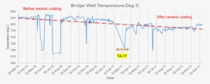
Steam generation control saw significant improvements, with radiant heat loss reduction leading to better efficiency and lower bridge wall temperatures by an average of 30-50°C (Table 2).
This improvement allowed for higher load operation while avoiding excessive steam generation and high heat loads on the convection steam coils.
Fuel efficiency also improved. Following the commissioning of a new refinery, the heaters transitioned to operating entirely on natural gas, with post-coating fuel consumption (MMBTU/hr) at 103% load proving lower than pre-coating requirements for 96-99% load operation (Table 3).


Financial Impact
The project demonstrated exceptional financial performance, achieving return on investment within just 6 months, significantly outperforming the projected 11-month timeline (Table 4). The internal return rate reached 111%, driven by cost benefits from both increased unit loads and fuel gas savings.
Long-Term Implementation and Continued Success (2017-2024)
The success of the initial ceramic coating implementation in 2017 led to several follow-up
projects, demonstrating the client’s continued confidence in the technology. In February 2022, a comprehensive recoating project was executed across all four cells of the CCR. This maintenance initiative involved applying Cetek M-600 high emissivity ceramic coating to the radiant tubes, ensuring the sustained performance benefits and tube integrity that had been established in the original implementation.
Most recently, in November 2024, the facility undertook a targeted upgrade of cell 2002, one of the four heater cells. This project involved the installation of new radiant tubes, which were subsequently treated with Cetek M-600 high emissivity ceramic coating. The decision to coat these new tubes immediately upon installation reflects the client’s strategic commitment to maintaining optimal operational efficiency and reliability across the entire facility.
These follow-up projects spanning from 2017 to 2024 demonstrate not only the long-term effectiveness of the ceramic coating solution but also its recognition as a standard best practice for maintaining and upgrading critical heater components. The continued investment in this technology underscores its role in achieving sustained operational excellence and equipment longevity in high-temperature processing environments.
Free consultation with an IGS Subject Matter Expert
IGS is here to provide information, answer questions and create an effective solution for your needs.