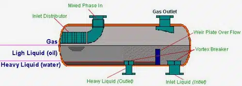
Pipelines that transport both gas and liquids together, known as two-phase flow, can operate in a flow regime known as slugging flow or slug flow. A slug catcher is a vessel with sufficient buffer volume to store the largest slugs expected from the upstream system. The slug catcher is located between the outlet of the pipeline and the processing equipment. The vessel is also used to separate out water from a production line.
A high pressure vessel taking feed directly from a production pipeline is employed to separate gas, oil and produced water. In order to provide corrosion resistance, the heavy wall slug catcher was strip weld overlayed with a 316SS alloy as originally manufactured. This overlay began to exhibit pitting corrosion. In order to protect the carbon steel from aggressive corrosion, it was necessary to prevent any further degradation.
The initial vessel fabrication required a 50-70mm thick carbon steel shell, lined with a strip welded 6mm 316SS weld overlay in the initial fabrication. As this material began to exhibit mild pitting, a permanent repair solution was sought. Localized applications of high temperature epoxy systems were not effective.
An offshore production platform contained two slug catchers that took oil/water/gas feed directly from the well. Having only seen several years of service, it was noted that shell pitting had occurred on the as-manufactured 316SS strip clad weld overlayed surface. The temperature and pressure service conditions precluded the use of any polymeric coating system.
The initial repair method considered was to weld overlay the shell with a second overlay cladding with a NiCrMo alloy. As an alternative, a high velocity thermal spray coating was also considered with a similar alloy. The thermal sprayed coating system was evaluated under similar process conditions and specified as an acceptable alternative.
Due to the tremendous cost associated with the replacement of two large vessels in the middle of a platform, two viable cladding solutions for this application were considered. The initial intent to weld-overlay the internal surface with an automated weld overlay procedure was not viewed favorably due to a required working window of 30 days in a field shutdown to effect the repair.
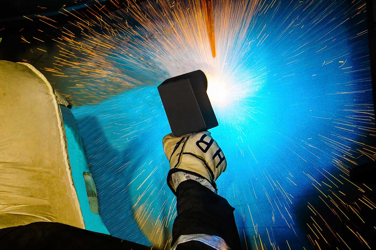
Thermal Spray was considered and after favorable test results a decision was made to coat the internal surface of the vessel with a High Velocity process as this only required 10 days of access which was within the original turnaround schedule. Due to the difficulty of satisfactory access of the thermal spray process to small bore nozzles, all nozzles 8” and lower were weld overlayed with an automated bore welding procedure. The welding process took place simultaneously to the internal coating.
Sour service conditions typically required post weld heat treatment per ISO15156, however, the procedure developed for the nozzle welding limited heat input through the existing 316SS to the carbon steel to maintain a low enough hardness and preclude any PWHT need. As the pitting was shallow, very little grinding was required to prepare the surface. Each vessel was shutdown serially, requiring careful work procedures associated with a live platform.
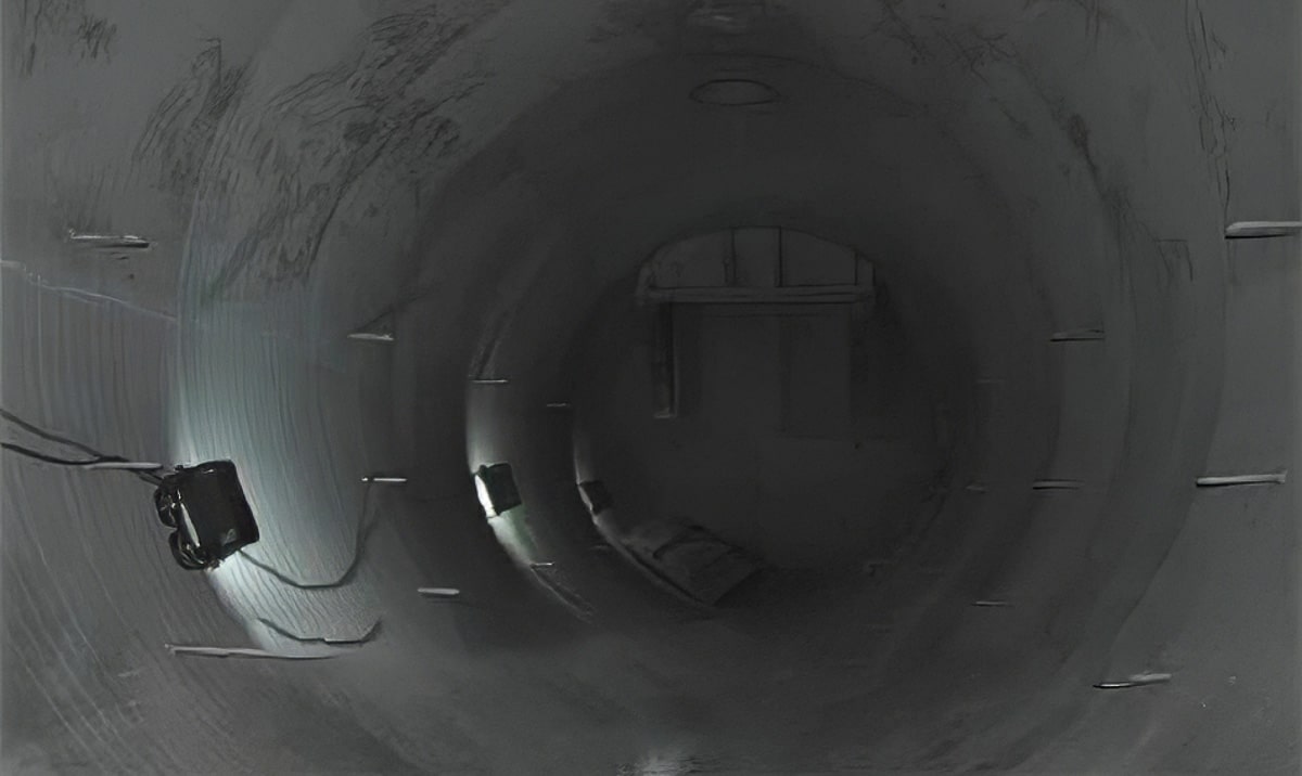
To mitigate corrosion of the slug catcher, IGS applied HVTS cladding to all internal surfaces and nozzles
Due to the non-magnetic substrate associate with the existing internal cladding, additional process controls were required to ensure even surface coverage. Welding procedures for the nozzles were required in all positions due to horizontal, inclined and vertically oriented positing. The largest nozzles welded were 8” and the smallest 1.6” internal diameter. Manways and flange faces were also protected with HVTS, and special masking was employed to protect the ring joint gasket faces.
After two and four year operational intervals, all thermal sprayed surfaces were carefully visually inspected for signs of corrosion in blisters or delamination. A visual inspection of nozzles was conducted with a borescope. No failure indications were identified.
Large heavy walled vessels on offshore production facilities are very difficult to replace or effectively repair over large surface areas. In this case, the inability of organic coating systems to stand up to the service conditions left only two options for upgrading the surface performance with a higher alloy system. The difficulties associated with weld overlay as well as the process difficulty associated with ensuring that PWHT was not required were considerable. The time required for this scope amounted to 20 days of additional field shutdown beyond the original scheduled turnaround.
The use of a high velocity thermal spray process was deemed more economical in direct cost and production losses when compared to this strategy. As both solutions were considered to be permanent fixes, the total life cycle cost savings associated with use of the faster less expensive technology was $7.78M, excluding opportunity cost.

Related Case Studies:
Related Questions:
On-site Thermal Spray Coating Services from IGS:
CATEGORIES: